
Secret Weapon 2008-2009 V6 ...
![Image]()
Dragon Intake 2008 V6 ...
![Image]()
Are these intakes really for the RAV4 V6? If so, has anyone tried them or know about the brand? What's the difference between the two models? It says they fit the '08 RAV4, why not the '06-'07's? here is a link to Andys Auto Sport ... http://www.andysautosport.com/toyota/2006_9999_rav_4/performance/intakes/air_intakes/weapon_r/
As many of us already know, they also make one for the 2007-2008 I4 ...
![Image]()
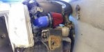
UPDATE: Pic installed in a V6 after being built by Weapon R ...
/forums/album_pic.php?pic_id=8491

Dragon Intake 2008 V6 ...

Are these intakes really for the RAV4 V6? If so, has anyone tried them or know about the brand? What's the difference between the two models? It says they fit the '08 RAV4, why not the '06-'07's? here is a link to Andys Auto Sport ... http://www.andysautosport.com/toyota/2006_9999_rav_4/performance/intakes/air_intakes/weapon_r/
As many of us already know, they also make one for the 2007-2008 I4 ...

UPDATE: Pic installed in a V6 after being built by Weapon R ...
/forums/album_pic.php?pic_id=8491


 (I know this may all sound confusing). A lot of stuff I tried/tested I don't talk about.


